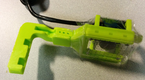
Manufacturing FingerVision
Overview †
FingerVision consists of a camera, a finger frame and a hard layer (transparent, e.g. acrylic), soft layer (transparent, e.g. silicone), and markers around the surface of the soft layer (e.g. black beads). Its manufacturing process consists of following steps:
- Make frames and molds with 3D printer
- Preprocess hard-layer
- Fixing the hard-layer on the finger frame
- Put markers on the mold
- Cast silicone into the mold, and put the finger frame
- Attach the camera
- Assemble the whole finger (Baxter finger only)
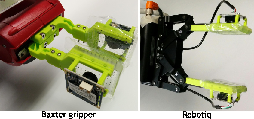
We designed FingerVision for Baxter electric parallel grippers (EPG) and Robotiq 2-Finger Adaptive Robot Gripper.
Ingredients †
The most of ingredients are common in Baxter EPG and Robotiq versions.
- Camera:
- ELP-USBFHD01M-L180, USB 2.0 camera with fisheye lens.
- Filaments of 3D printer
- Filament for frames: PolyLite PLA LulzBot Green
- Filament for mold: PolyLite PLA Translucent Blue or Red
- Silicone:
- Silicones, Inc., XP-565, transparent, shore hardness A-16.
- ComposiMold
- Reusable mold for casting silicone.
- Black plastic beads:
- American Crafts-Microbeads, approx. 1 mm diameter.
- Acrylic plate:
- Transparent, 2 mm thickness, 31 mm x 40 mm.
- Plastic film for protecting FingerVision from dirt:
- Plastic wrap for food is okay, such as ClingWrap.
- Screws and nuts:
- 8 x Screws (#2-56 x 5/16 inch) for fixing the acrylic layer and the finger frame, and attaching a camera.
- 2 x Screws (#2-56 x 3/4 inch) for assembling (Baxter EPG version only).
- 4 x Nuts (#2-56) for fixing the acrylic layer.
- 2? x Nuts (#2-56) for assembling (Baxter version only).
- 3 x Screws (#2-56 x ??? inch) for assembling (Robotiq version only).
- 3 x Nuts (#2-56) for assembling (Robotiq version only).
Tools †
- 3D printer:
- Vacuum (for degassing to remove air bubbles in silicone):
- Scale to measure silicone resin
- Drill (3/32 inch)
- Tap (#2-56 and 1/4"-20) for creating screw threads
- 2 x Screws (1/4"-20) for fixing the frame during curing silicone
- 2 x Nuts (1/4"-20) for fixing the frame during curing silicone
Making Frames and Molds †
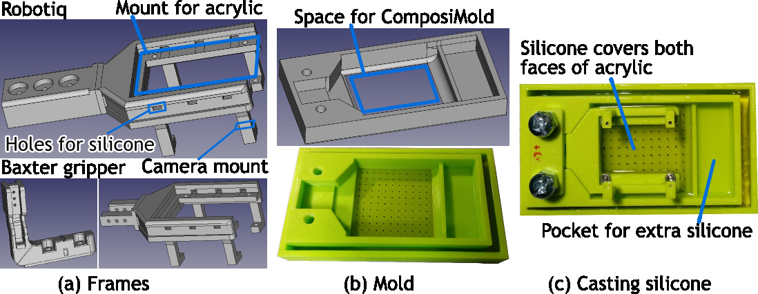
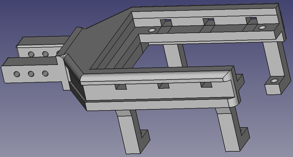
The CAD models are available on GitHub (CAD files are in the cad/ directory). Print frames and molds for Baxter EPG or Robotiq gripper.
Baxter electric parallel gripper (EPG):
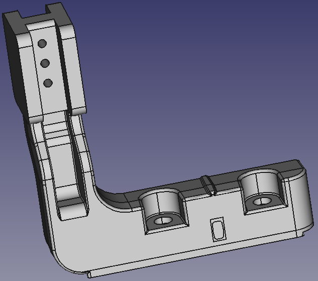
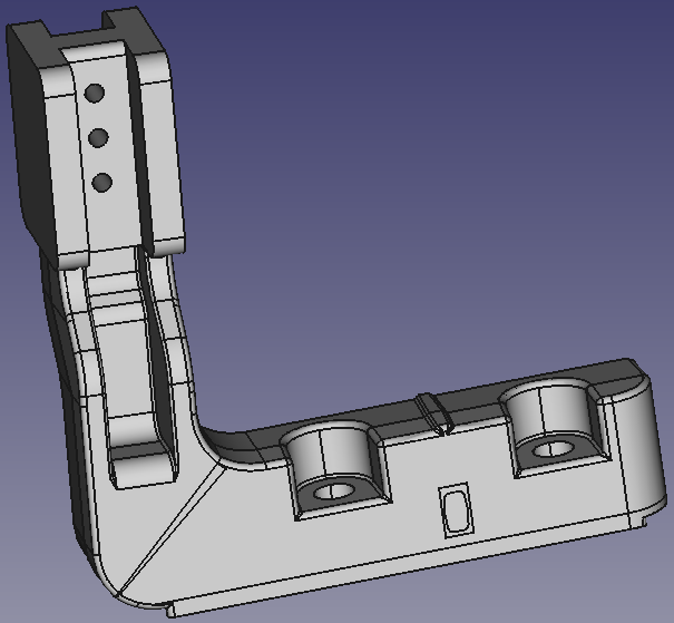
- bxgr_optskin02{a,b}: Finger frames (a,b) (REFERRED TO AS: frame_{a,b})
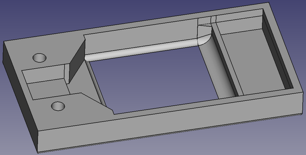
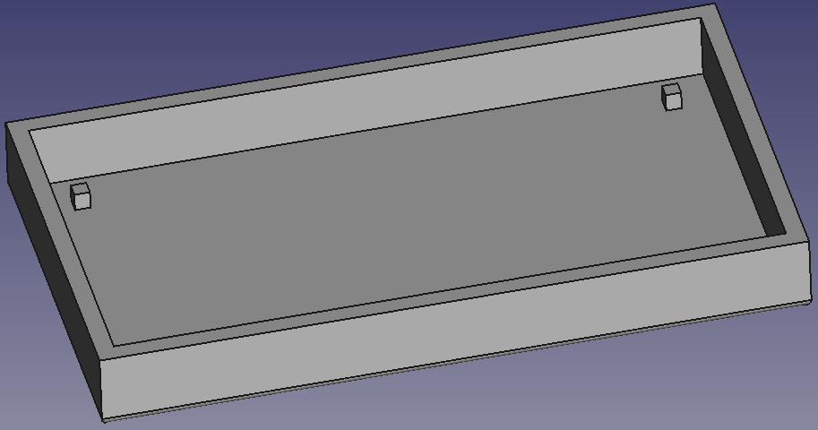
- bxgr_optskin02_mold_{a,b,c,d}: For making a mold (REFERRED TO AS: mold_{a,b,c,d})
- bxgr_optskin02c: Drill guide for frames_a (REFERRED TO AS: guide_c)
- Note
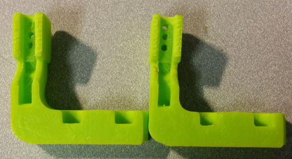
- bxgr_optskin02b has two versions: straight (bxgr_optskin02b-v3) and angled (bxgr_optskin02b-v3.1). Both are very similar except for the angle between the base and the finger; straight: 90 deg, angled: 87 deg. Since the fingers bend slightly during grasping an object, we created an angled version to compensate that (so angled version is recommended).
Left: straight, Right: angled.
Robotiq gripper:
- rq_optskin01a: Finger frame (REFERRED TO AS: frame_a)
- rq_optskin01_mold_{a,b}: For making a mold (REFERRED TO AS: mold_{a,b})
- bxgr_optskin02_mold_{c,d}: For making a mold (REFERRED TO AS: mold_{c,d})
- bxgr_optskin02c: Drill guide for frames_a (REFERRED TO AS: guide_c)
| frame_a | |||
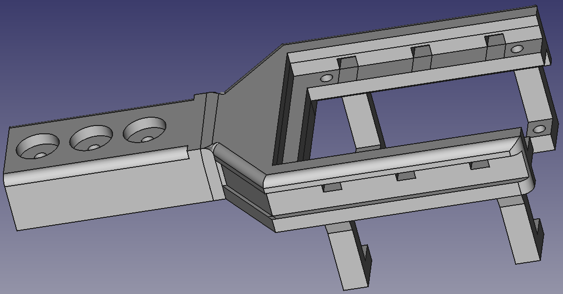 rq_optskin01a | |||
| mold_a | mold_b | mold_c | mold_d |
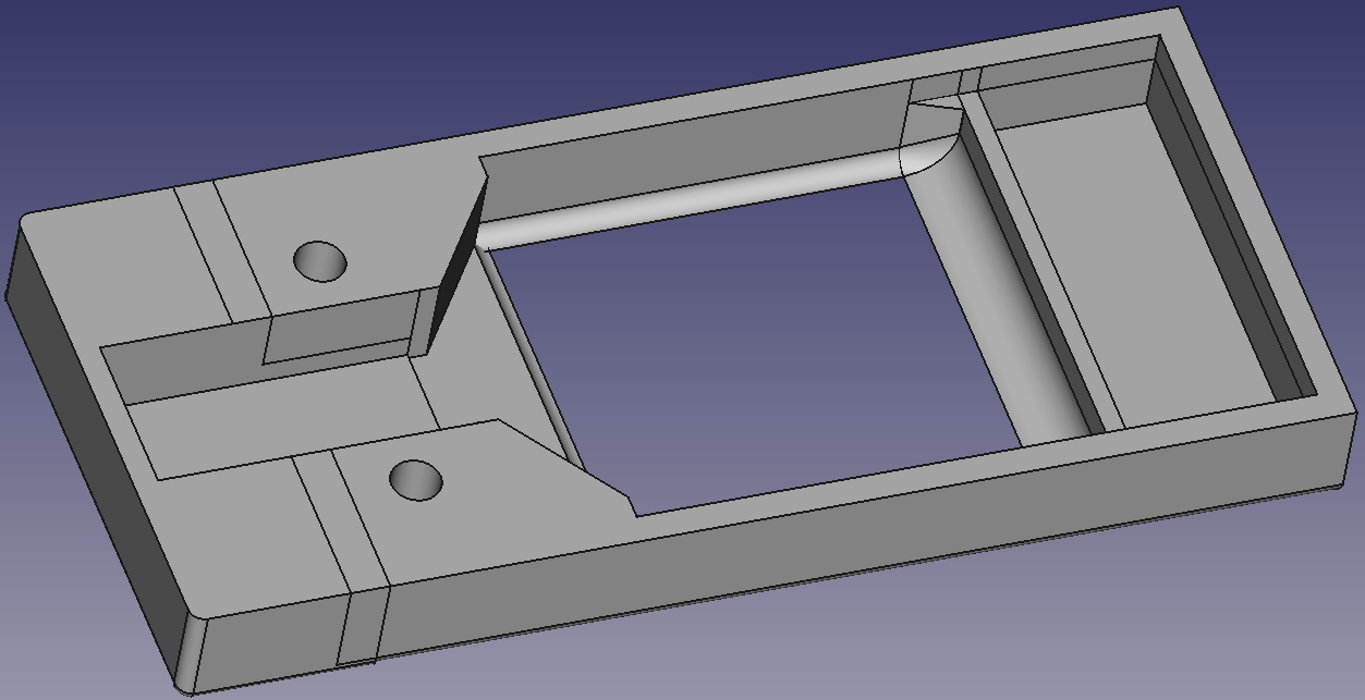 rq_optskin01_mold_a | 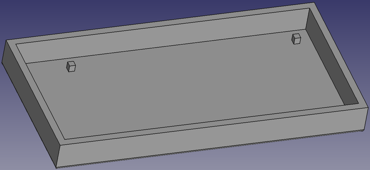 rq_optskin01_mold_b | 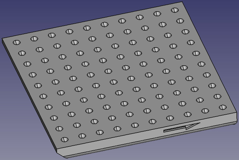 bxgr_optskin02_mold_c-v3(cmn) | 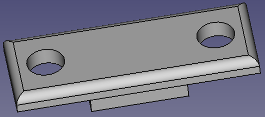 bxgr_optskin02_mold_d-v3(cmn) |
| guide_c | |||
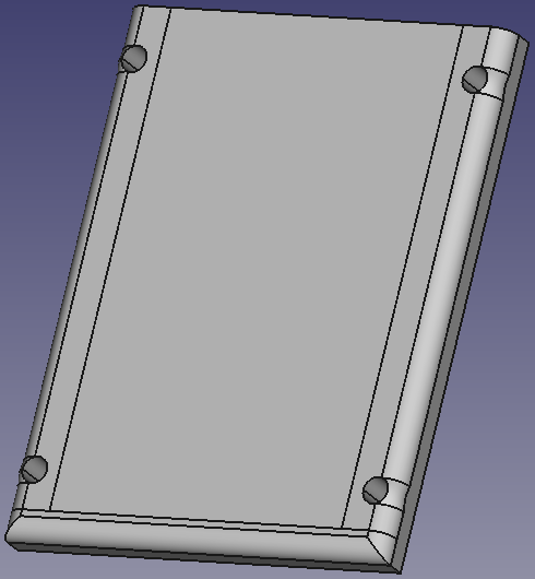 bxgr_optskin02c-v3.1(cmn) |
(cmn) denotes the CAD model is common with that of Baxter EPG.
We need post-processes.
Drill:
- Acrylic and frame, use the drill guide
- Connection between the finger tip frame and finger base frame (Baxter version)
- Connection of Robotiq gripper
Tap:
- Camera mount
- Mold
Compisimold for the bottom of 3D printed mold.
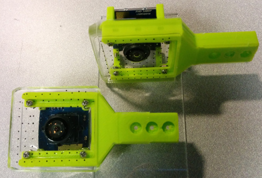
Fix the acrylic place on the finger frame with screws.
Casting Silicone †
- Place the markers; use the marker placing guide
- Mixing silicone
- Vacuuming silicone
- Pour into the mold
- Put the finger tip frame
- Pour silicone more to cover the opposite side
- Wait 12 hours for curing silicone
Assembly †
Assembling Camera †
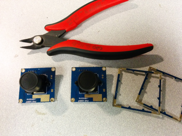
Remove the outer rim of the camera.
Before mounting the camera, adjust the focus of the camera. It should be done manually. Capture the camera image with PC (e.g. use guvcview on Linux). We recommend to adjust the focus on the markers when assembling the camera.
Mount the camera with four screws on the camera mount of the finger frame. Nuts are not needed because we created the screw threads.
Finally cover the FingerVision with a thin plastic film.
Assembling Baxter Finger Base †
The FingerVision for Baxter electric parallel gripper (EPG) is divided into two parts: finger tip and finger base. There are two versions of the finger base: straight (90 deg) and angled (87 deg). See the CAD model explanation.
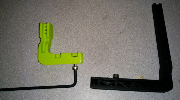
First, detach the screws from the original Baxter EPG finger. Attach the screws into the holes of the finger base. (Tips: In order to make screw threads, insert the screw from the opposite side and screw. Then insert the screw from the right way.)
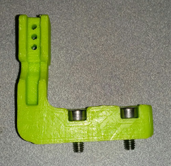
Assemble the finger tip (FingerVision) and the finger base with screws.
Pic: The screws are not attached yet. Use two pairs of screws and nuts.
